
- トップ
- 自己紹介,about
- 業務内容,business
- お知らせ,news
- 技術小論,articles
- 技術小論
- 記事
- スペアナ周波数特性点検システム
- アレイアンテナの指向性
- 並列共振回路
- 屋内半固定通信の弱電界領域への対応
- 試作時の細かい加工例
- デジタルマルチメーターの性能比較2
- DFTの定義が異なる理由
- デジタルマルチメーターの性能比較
- 無線分野の技師が扱ふ技術領域
- スミスチャートによる整合回路設計
- スミスチャートによる直並列変換
- アンダーサンプリングによる周波数移動と標本化周波数の低減
- オームの法則に従はない実験
- シート状導体の抵抗を電磁界シミュレーターで解析する
- 平行平板コンデンサを電磁界シミュレーターで解析する
- 平行平板コンデンサを電磁界シミュレーターで解析する2
- 平行平板コンデンサを電磁界シミュレーターで解析する3
- 平行平板コンデンサを電磁界シミュレーターで解析する4
- 導体と絶縁体の区分
- 電磁界シミュレーターによる静電容量式タッチセンサーの電極考察
- 分布定数回路理解のための電子工学
- リンク,links
- English,English
- SITEMAP


A planar capacitor analysis by EM simulator 1
Abstract
A planar capacitor--a parallel-plate capacitor is seen in a textbook of electromagnetics. But I have scarcely seen modified ones other than the basic type. For example, electrodes of a capacitor are horizontally shifted or have different size or shape from the other one. In textbooks such problems may be left to readers as an exercise.Here I used an electromagnetic simulator and analyzed the variation of capacitance of a planar capacitor. I used Sonnet Lite of Sonnet Software Inc. here as well as my touch sensor analysis.
These results show that electric lines which flow out from the edge of electrodes are not negligible in a capacitor which has a complicated-shape electrode such as a comb or a mesh, and that estimation of its capacitance is not simple.
Contents
1. Shifted-electrodes capacitor
1.1 Base point--the nornal case
1.2 75% overlappping capacitor
1.3 50% overlappping capacitor
1.4 25% overlappping capacitor
1.5 0% overlappping capacitor
1.6 -25% overlappping capacitor
1.7 Capacitance vs. overlapping ratio
1.8 Local conclusion
2. Different-size electrodes capacitor
2.1 Expectation of the result
2.2 Analysis result
2.3 Local conclusion
3. Single comb-shape electrode capacitor
3.1 Expectation of the result
3.2 Analysis result
3.3 Supposition of the reason for error
3.4 Local conclusion
4. Single mesh-shape electrode capacitor
4.1 Expectation of the result
4.2 Analysis configuration
4.3 Analysis result
4.4 Supposition of the reason for error
4.5 Local conclusion
5. Conclusion
1 Shifted-electrodes capacitor
First I analyzed a planar capacitor of which both of electrodes are the same size. How much does the overlapping ratio of a pair of electrodes affect the capacitance?1.1 Base point--the nornal case
First I analyzed a basic shape capacitor.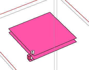
Fig. 1.1
The descriptions are:
| Area of an electrode | 10mm*10mm |
| Gap height between electrodes | 0.1mm |
| Dielectric in the gap | air |
| Overlapping ratio of electrodes | 100% |
I got 1734 ohms at 10MHz. The capacitance was 9.18pF. This is the base point data.
1.2 75% overlappping capacitor
Second I analyzed a capacitor of which electrodes overlapped 75%.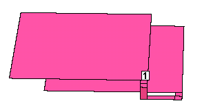
Fig. 1.2
I got 2242 ohms at 10MHz. The capacitance was 7.10pF.
1.3 50% overlappping capacitor
Third I analyzed a capacitor of which electrodes overlapped 50%.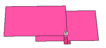
Fig. 1.3
I got 3251 ohms at 10MHz. The capacitance was 4.90pF.
1.4 25% overlappping capacitor
Fourth I analyzed a capacitor of which electrodes overlapped 25%.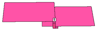
Fig. 1.4
I got 5925 ohms at 10MHz. The capacitance was 2.69pF.
1.5 0% overlappping capacitor
Fifth I analyzed a capacitor of which electrodes overlapped 0%.
Fig. 1.5
I got 34.008k ohms at 10MHz. The capacitance was 0.468pF.
1.6 -25% overlappping capacitor
Sixth I analyzed a capacitor of which electrodes overlapped -25%. This is just for a reference.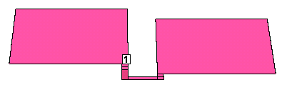
Fig. 1.6
I got 46.417k ohms at 10MHz. The capacitance was 0.343pF.
1.7 Capacitance vs. overlapping ratio
Here I put the summary table.| Overlapping ratio of electrodes | 100% | 75% | 50% | 25% | 0% |
| Figure | |
 |
 |
|
|
| Estimated capacitance | 9.18pF | 7.10pF | 4.90pF | 2.69pF | 0.468pF |
| Ratio of capacitance | 100% | 77% | 53% | 29% | 5% |
| Error to the overlapping ratio | N/A | 2% | 3% | 4% | 5% |
We understand that the capacitance of a planar capacitor changes in proportion to the overlapping ratio of electrodes. But some error exists.
Then I subtracted the number of the capacitance in 0% from other cases. Then the table changed like below:
| Overlapping ratio | 100% | 75% | 50% | 25% | 0% |
| Capacitance subtracted 0.468pF | 8.71pF | 6.63pF | 4.43pF | 2.22pF | N/A |
| Ratio of capacitance | 100% | 76% | 51% | 26% | N/A |
Fig. 1.7
Actually we have electric field which flows out from the perimeter of electrodes. So we have 0.468pF even though the overlapping ratio is 0%.
That is, in each case the electric field which flows out from the edge of the electrodes almost equals to the capacitance in the 0%-overlapped case.
1.8 Local Conclusion
Capacitance of a planar capacitor changes in proportion to the overlapping ratio of electrodes.Issued on August 21, 2009